
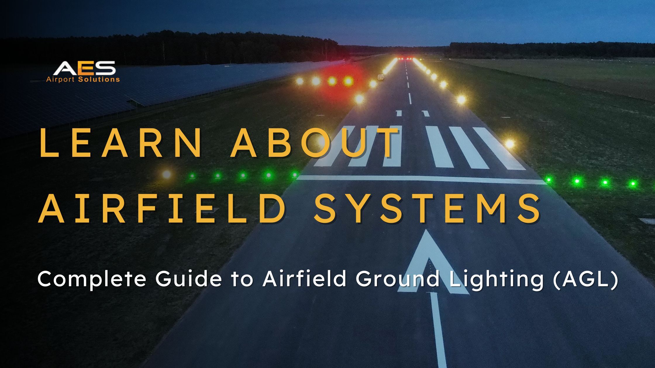
Airfield ground lighting (AGL) is the network of lights, signs, and visual aids installed on and around an airport’s runways, taxiways, and aprons. Its purpose is to provide pilots and ground crews with the visual references they need to operate safely, particularly at night and in reduced visibility conditions.
An AGL system is not a single product. It is an integrated infrastructure made up of dozens of different light types, each with a specific function, colour, intensity, and position on the airfield. Together, they form a visual language that pilots worldwide rely on every time they land, take off, or taxi.
This guide covers each major component of an AGL system, from the approach path all the way to the gate.
1. Approach Lighting Systems
The approach lighting system is the first set of lights a pilot sees when descending towards the runway. It is located on the extended centreline of the runway, starting several hundred metres before the threshold and leading towards it.
Its job is to provide a visual transition from instrument flight (where the pilot is flying by reference to cockpit instruments) to visual flight (where the pilot can see the runway environment). This transition is critical during precision approaches, especially in low visibility.
Types of Approach Lighting Systems
There are several approach lighting configurations, and the type installed depends on the approach category of the runway.
Simple approach lighting consists of a centreline of steady white lights with a crossbar, typically used for CAT I runways. It extends about 420 to 720 metres before the threshold and gives the pilot a basic visual lead-in.
ALSF-1 and ALSF-2 (Approach Lighting System with Sequenced Flashing Lights) are more complex systems used for CAT I and CAT II/III operations respectively. They combine steady centreline lights with sequenced flashing lights (often called «rabbit lights» because the flash pattern appears to run towards the runway like a ball of light). ALSF-2, used for the most demanding low-visibility approaches, extends 900 metres before the threshold and includes red side bars in the last 300 metres.
CALVERT systems are widely used in Europe and follow ICAO standards. They use a pattern of centreline lights with crossbars at specific distances that helps the pilot judge alignment and distance to the threshold.
SALS (Short Approach Lighting System or Simple Approach Lighting System) and SSALS (Simplified Short Approach Lighting System) are simplified versions used at airports where a full system is not required or not practical due to terrain or space limitations.
Sequenced Flashing Lights (SFL)
Most precision approach lighting systems include sequenced flashing lights. These are high-intensity white strobe lights that flash in rapid sequence from the outer end of the approach path towards the runway. The effect is a visible pulse of light that «runs» towards the threshold, giving the pilot a powerful directional cue even in very poor visibility.
Runway Threshold Identification Lights (RTIL)
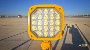
Some runways also have runway threshold identification lights, which are a pair of synchronised flashing white lights on either side of the threshold. They help pilots identify the exact start of the landing surface, particularly at airports where the approach environment may be confusing due to surrounding lighting.
2. Visual Approach Slope Indicators (PAPI and VASI)
Before a pilot reaches the approach lighting system, they need to know if they are on the correct glide slope. This is the job of the visual approach slope indicator.
PAPI (Precision Approach Path Indicator)
The PAPI is the most common system in use today. It consists of four light units installed on one side of the runway, roughly 300 metres from the threshold. Each unit projects a beam that appears either red or white depending on the angle at which the pilot views it.
If the pilot sees four white lights, they are too high. Four red means too low. Two red and two white means they are exactly on the correct 3-degree glide path. The transition between red and white happens within an extremely narrow angle (3 minutes of arc), which makes the PAPI one of the most precise visual instruments on the airfield.

VASI (Visual Approach Slope Indicator)
The VASI is an older system that uses a similar red/white principle but with a different arrangement. Instead of four units in a single row, VASI typically uses two bars of lights (near and far) at different distances from the threshold. If the far bar shows white and the near bar shows red, the pilot is on the correct path. VASI is gradually being replaced by PAPI at most airports, but it is still found at some older installations.
3. Runway Lighting
Once the aircraft crosses the threshold, it enters the runway environment. Runway lighting provides the visual references the pilot needs for landing, rollout, and takeoff.
Runway Edge Lights
These are elevated white lights installed along both sides of the runway for its full length. They define the lateral limits of the runway and are visible from long range. In the last 600 metres of the runway (or last third, whichever is less), the edge lights change from white to yellow to warn the pilot that the runway end is approaching.
Runway edge lights are classified by intensity. High-intensity runway lights (HIRL) are used at airports with precision approach runways. Medium-intensity (MIRL) and low-intensity (LIRL) are used at smaller airports or runways with less demanding approach procedures.
All runway edge lights are mounted on frangible couplings so they break away cleanly if struck by an aircraft wheel or wing.

Runway Centreline Lights
These are in-pavement (inset) white lights installed along the exact centre of the runway at intervals of approximately 15 metres. They provide precise alignment guidance during landing and takeoff, particularly in low visibility.
In the last 900 metres of the runway, the centreline lights transition from white to alternating red and white. In the final 300 metres, they become solid red. This colour transition gives the pilot a clear warning of how much runway remains.
Centreline lights are required for CAT II and CAT III operations and are recommended for CAT I.
Threshold and End Lights
Threshold lights are a bar of green lights across the full width of the runway at the landing threshold. They tell the pilot: this is where the runway begins. Viewed from the approach, they are green. Viewed from the runway (by an aircraft taking off), the same fittings show red, serving as runway end lights for the opposite direction.
At runways where the threshold is displaced (moved further along the runway for landing purposes), the edge lights between the physical start of the pavement and the displaced threshold show red to approaching aircraft.
Touchdown Zone Lights (TDZ)
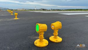
Touchdown zone lights are in-pavement light bars installed in the first 900 metres of runway beyond the threshold. They are arranged as transverse pairs on each side of the centreline at 30-metre intervals, creating a visible «ladder» pattern that gives the pilot a strong sense of height and alignment during the final seconds before touchdown.
TDZ lights are mandatory for CAT II and CAT III runways. They provide the critical visual bridge between the approach lighting system (which ends at the threshold) and the runway centreline lights.
4. Taxiway Lighting
Once the aircraft has landed and decelerated, it exits the runway and enters the taxiway system. Taxiway lighting guides the aircraft safely from the runway to the gate and back.
Taxiway Edge Lights
Blue elevated lights that mark the edges of taxiways. They are visible from all directions (omni-directional) and define the lateral boundaries of the taxiway surface. Blue is used exclusively for taxiway edges and is one of the most recognisable colours on any airfield at night.
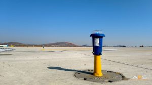
Taxiway Centreline Lights
Green in-pavement lights installed along the centre of the taxiway. They guide the pilot along the correct path, which is particularly important at complex airports with many intersecting taxiways. At points where a taxiway intersects a runway, the centreline lights alternate green and yellow to warn the pilot they are approaching a runway environment.
Stop Bars
A row of red in-pavement lights installed across the full width of a taxiway at a runway holding position. When lit, they tell the pilot they must stop and not enter the runway. When extinguished (by air traffic control), the pilot is cleared to proceed. Stop bars are a critical tool in preventing runway incursions, which are among the most serious safety risks at any airport.
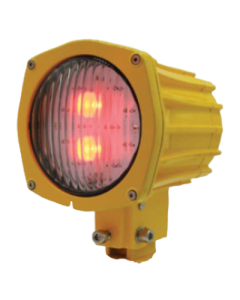
Runway Guard Lights
Flashing yellow lights installed at taxiway/runway intersections. They come in two configurations: elevated pairs of flashing yellow lights on either side of the taxiway («wig-wags»), and in-pavement yellow lights across the taxiway width. Their function is to alert pilots and ground vehicle drivers that they are approaching an active runway.
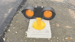
Clearance Bars and Lead-Off Lights
Clearance bar lights are in-pavement yellow lights installed at holding positions other than runway holding positions (for example, at intermediate holding points on complex taxiway systems). Taxiway centreline lead-off lights are alternating green and yellow in-pavement lights that guide aircraft from the runway centreline to the taxiway centreline during runway exit.
5. Taxiway Guidance Signs
LED taxiway guidance signs are illuminated signs installed at taxiway intersections, runway holding positions, and key navigation points on the airfield. They tell pilots where they are and where each taxiway leads.
Mandatory Signs
These have white text or symbols on a red background. They identify critical locations such as runway designations at holding positions (for example, «22-04» indicating the runway numbers) and ILS critical areas. Pilots must comply with the instruction on a mandatory sign unless cleared by ATC.
Location Signs
Yellow text on a black background. They tell the pilot which taxiway they are currently on, providing a «you are here» reference.
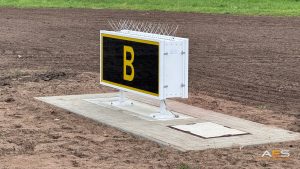
Direction and Destination Signs
Black text on a yellow background. They indicate which taxiways or destinations (terminal, apron, runway) are available ahead and in which direction. An arrow accompanies each designation.
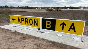
All modern guidance signs use LED light sources for sharp visibility, low energy consumption, and long operational life. The signs are mounted on frangible poles to meet ICAO and FAA breakaway safety requirements.
6. Power Supply: Constant Current Regulators (CCR)
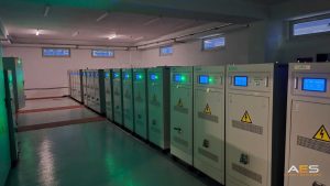
All of the lights described above need a reliable and precisely regulated power supply. That is the job of the constant current regulator (CCR).
Why Series Circuits?
Airport lighting circuits are wired in series, not in parallel like domestic or commercial lighting. In a series circuit, the same current flows through every lamp. If one lamp fails, the circuit is not broken because each lamp has a bypass device (called an isolation transformer) that keeps the current flowing.
The advantage of series circuits for airfield lighting is consistency. Every lamp in the circuit receives the same current, which means they all produce the same light intensity. This is critical because ICAO and FAA standards require specific candela output at each lamp position, and any variation could affect pilot visibility.
What a CCR Does
A CCR takes the incoming mains voltage (typically 220/400V AC at 50/60Hz) and converts it into a regulated constant current output (standardised at 6.6A for high-intensity circuits). It maintains this current regardless of how many lamps are connected or how long the circuit is.
CCRs also provide brightness control. By adjusting the output current in steps (typically 3 to 6 brightness levels), the CCR allows air traffic control to increase or decrease the intensity of the runway lighting to match visibility conditions. At night in clear weather, a lower setting avoids glare. In fog, the maximum setting ensures the lights are visible at the required distance.
Modern CCRs include features such as lamp fault detection (identifying which specific lamp in a circuit has failed), insulation resistance monitoring, remote control via Modbus or PROFIBUS, and touchscreen interfaces for configuration and diagnostics.
7. Obstruction Lighting
Not all airfield lighting is on the ground. Obstruction lights are installed on buildings, towers, cranes, and other structures in the vicinity of an airport that could pose a hazard to aircraft.
ICAO and national regulations define when obstruction lighting is required based on the height and proximity of the structure to the aerodrome. The lights are categorised by intensity:
Low-intensity obstruction lights are steady red lights used on structures below 45 metres. Medium-intensity lights are flashing white (daytime) and red (night) lights for structures between 45 and 150 metres. High-intensity lights are flashing white lights used on structures above 150 metres, such as telecommunications towers and wind turbines.
8. Helipad Lighting
Helipad lighting has its own set of requirements, defined primarily in ICAO Annex 14 Volume II. The key components include TLOF (Touchdown and Lift-Off area) perimeter lights, which are typically green and mark the area where the helicopter makes contact with the surface, and FATO (Final Approach and Take-Off area) lights, which mark the broader area used for the approach and departure.
Helipad lighting is used at hospital helipads, offshore platforms, military installations, and rooftop helipads in urban areas. The fittings must be able to withstand rotor downwash and, for elevated helipads, significant wind exposure.
9. Solar Airfield Lighting
Solar airfield lights are a relatively recent addition to the AGL landscape. They operate independently from the electrical grid, using integrated solar panels and lithium batteries to provide autonomous lighting for extended periods.
Solar AGL is used in situations where traditional cabled infrastructure is not available, not practical, or not cost-effective. Typical applications include remote airfields without grid access, temporary runway closures where lights need to be redeployed, military operations requiring rapid deployment, helipad lighting at isolated locations, and emergency or humanitarian deployments.
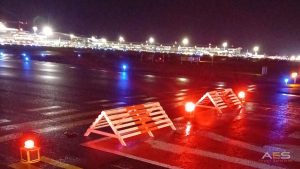
Modern solar airfield lights can deliver full ICAO and FAA compliant photometric performance, with battery autonomy reaching over 30 hours on a single charge for high-intensity units and over 480 hours for low-intensity taxiway edge markers.
10. LED vs Halogen: The Industry Shift
For most of its history, airfield lighting used halogen or incandescent lamp technology. Over the past decade, the industry has been transitioning to LED across virtually every application.
The advantages of LED are significant. Energy consumption drops by 40 to 60% for the same light output. Operational life increases from 1,000 to 2,000 hours (halogen) to 60,000 to 100,000 hours (LED). Colour consistency is maintained throughout the life of the LED, while halogen lamps shift towards yellow as they age. And maintenance requirements are reduced dramatically, which means fewer runway closures for lamp changes.
The one area where halogen retains a functional advantage is in extreme cold climates, where the waste heat from halogen lamps helps melt snow and ice from the lens surface. LED fittings are too efficient to generate this heat naturally, which is why arctic kits (thermostatically controlled heating elements) are available as an option for LED fittings used in cold environments.
11. Standards and Compliance
Airfield ground lighting is one of the most heavily regulated areas of airport infrastructure. The key standards that govern AGL design, performance, and installation are:
ICAO Annex 14, Volume I (Aerodrome Design and Operations) is the global baseline. It defines where lights must be placed, what colours they must be, and what photometric performance they must achieve.
FAA Advisory Circulars (AC 150/5345 series) provide detailed specifications for individual light types used at airports in the United States and at many airports worldwide that follow FAA standards.
FAA Engineering Brief EB 67D covers the requirements for LED and non-incandescent light sources, including arctic testing for cold-climate fittings.
EASA CS-ADR-DSN is the European certification specification for aerodrome design, based on ICAO standards with European-specific additions.
IEC TS 61827 is the international technical specification for electrical installations for airfield lighting and beaconing.
STANAG 3316 is the NATO standard for military airfield lighting.
FAQ
Q: What is airfield ground lighting (AGL)? A: Airfield ground lighting is the system of lights, signs, and visual aids installed on airport runways, taxiways, and surrounding areas to provide visual guidance to pilots and ground crews, particularly during night operations and low-visibility conditions.
Q: What are the main components of an AGL system? A: A complete AGL system includes approach lighting, visual approach slope indicators (PAPI/VASI), runway edge and centreline lights, threshold and end lights, touchdown zone lights, taxiway edge and centreline lights, stop bars, guidance signs, constant current regulators (CCR), and obstruction lighting.
Q: What colour are taxiway edge lights? A: Taxiway edge lights are blue. This colour is used exclusively for taxiway edges and is one of the most recognisable visual cues on any airfield at night.
Q: What is a PAPI and how does it work? A: A PAPI (Precision Approach Path Indicator) is a visual aid that helps pilots maintain the correct glide slope during approach. It consists of four light units that appear red or white depending on the viewing angle. Two red and two white means the pilot is on the correct path.
Q: Why do airports use series circuits for AGL? A: Series circuits ensure that every lamp in the circuit receives the same current, producing consistent light intensity across all positions. This is critical because aviation standards require specific candela output at each lamp location.
Q: What is the difference between LED and halogen airfield lights? A: LED airfield lights consume 40 to 60% less energy, last 60,000 to 100,000 hours compared to 1,000 to 2,000 for halogen, maintain consistent colour output, and require significantly less maintenance. Halogen retains an advantage in extreme cold climates due to its natural heat output that helps melt snow from the lens.